
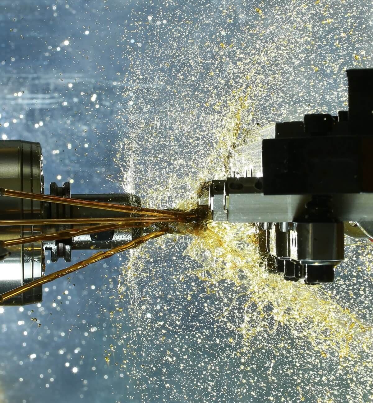
The lathe is one of the oldest machine tools in existence. People have been turning metal since the ancient Egyptians used bow-driven lathes to shape wood and stone. The basic principle has not changed. A workpiece spins while a cutting tool removes material to create a cylindrical shape. What has changed is the level of control we have over that process.
The Digital Difference
CNC Turning takes that ancient concept and adds a layer of digital command that transforms what a lathe can do. The computer numerical control system stores a program that directs every movement of the cutting tool. The spindle speed, the feed rate, the tool path, the depth of cut, all of these parameters are written into code and executed the same way on every cycle. The machine doesn’t interpret or adjust based on feel. It follows the instructions and produces parts that match one another with remarkable consistency.
Consistency Over Skill
That consistency is what sets CNC Turning apart from manual turning. A skilled manual machinist can produce beautiful work. They can hold tight tolerances and make parts that function perfectly. But they cannot do it the same way every time, on every part, across a production run of hundreds or thousands of pieces.
Human hands introduce variation. The machinist might take a slightly heavier cut on one part and a lighter cut on the next. They might sharpen the tool at a slightly different angle. They might read the micrometer with a slightly different eye. These things are simply the nature of manual work.
CNC Turning eliminates that variation by removing the human hand from the cutting process. The operator still loads the material, starts the cycle and checks the parts. But the cutting itself follows a fixed sequence of motions. This means every part gets the same treatment. The first part off the machine matches the hundredth part, provided the tool does not wear beyond acceptable limits and the setup remains stable.
Capabilities Beyond Simple Turning
The range of work you can do on a CNC lathe extends far beyond straight cylindrical turning. With the right tooling and programming, you can cut tapers, contours, threads, grooves and knurls. You can drill and bore holes along the centerline. With live tooling, you can mill flats, drill cross-holes and tap threads without removing the part from the machine.
This capability reduces handling time and eliminates the positional errors that occur when you move a part between different workstations.
Materials and Their Behavior
At Topcraft, we run a variety of materials through our CNC turning equipment. Alloy steel, aluminum, brass, copper, nickel, stainless steel, tin and zinc all come through the shop. Each material behaves differently under the cutting tool. Some are gummy and require sharp edges and light feeds. Some are hard and generate significant heat. Some produce long, stringy chips that wrap around the tool.
The CNC program accounts for these differences through adjustments to speeds, feeds and tool paths. The machine does not care what material you give it. The program tells it what to do and it does that thing the same way every time.
Types of CNC Lathes
The equipment itself comes in several configurations, from turret-style lathes that hold multiple tools and index them into position automatically, to gang-style lathes that arrange tools in a row and move the tool post to bring each one into the cut. Both approaches have their place depending on the part geometry and production volume but what they share is the CNC control that directs their movements with repeatable precision.
The Measurement Problem
But repeatable cutting is only half the story. If you can’t measure what the machine produces, you don’t know whether you are making good parts. But even if a CNC lathe might hold its tolerances beautifully, you can’t trust the process if your measurement system gives you bad numbers.
You might scrap good parts because the gage reads them out of tolerance. You might ship bad parts because the gage reads them in tolerance. Either way, the measurement system is the weak link.
What Is a Gage R&R Study?
This is why Topcraft uses Gage Repeatability and Reproducibility studies to validate our inspection methods. The Gage R&R study answers a direct question: when you measure the same part repeatedly, do you get the same result? If the measurement system introduces too much variation, you can’t trust the numbers it produces.
Repeatability Versus Reproducibility
The study breaks measurement variation into the two categories, repeatability and reproducibility. Repeatability looks at variation caused by the measurement device itself. If the same operator measures the same part with the same gage, how much does the reading vary from one measurement to the next? Reproducibility looks at variation between operators. If two different people measure the same part with the same gage, do they get the same reading?
How the Study Works
A typical Gage R&R study involves three operators measuring ten parts three times each, for a total of ninety measurements. The parts should span the expected range of variation in production. The operators should represent the people who will actually use the gage.
The analysis produces a percentage that tells you how much of the observed variation comes from the measurement system rather than from the parts themselves. The Automotive Industry Action Group recommends that the combined repeatability and reproducibility be 10% or less of the total variation. Above 30% is considered unacceptable for most applications.
What the Results Tell Us
At Topcraft, we run these studies on our inspection equipment to verify that our measurements are trustworthy. The results tell us when a gage needs recalibration or when an operator needs more training.
Measurement error can consume a significant portion of your tolerance band if you are not careful. If your tolerance is ±0.001 inches and your measurement system has uncertainty of 0.0005 inches, half your tolerance is gone before you even start manufacturing. You are essentially trying to hold ±0.0005 inches in the actual cutting process to end up within ±0.001 inches at inspection. That is a difficult way to work.
Finding the Root Cause
The Gage R&R study also helps identify the root causes of measurement problems. If the reproducibility component is high, you might have operators using different techniques. If the repeatability component is high, the gage itself might be unsuitable for the application.
Sometimes the issue is a part that deforms under the pressure of the measurement tool. Sometimes it is an out-of-round condition that gives different readings depending on where you measure the diameter.
Why Measurement Matters for CNC Turning
CNC Turning demands this level of attention to measurement because the processes are capable of holding tight tolerances. The machine can produce parts that meet your specifications. But to know that, you need to measure them with a system you trust. The Gage R&R study gives you that trust by quantifying the uncertainty in your inspection process.
Bringing It All Together
The combination of CNC control, proper tooling, suitable materials and validated inspection creates a system that givs consistent results. The machine follows the program, tools cut the material and the measurement system verifies the outcome.
Each part is a data point and over time, those data points tell you whether the process is under control and producing the quality you need. This is what CNC Turning offers: a repeatable, documented and trustworthy way to make cylindrical parts that meet the requirements of the people who use them.